Tu sei qui
Parametric Nailing
I disegni esecutivi delle pareti e dei solai della casa di “RhOME for denCity” (Solar Decathlon 2014) comprendono il disegno delle chiodature (o “cambrettature”). Queste assicurano la solidarietà dei pannelli di rivestimento in materiale “Superpan” ai montanti delle pareti (o travetti nel caso del solaio).
The executive drawing of walls and floor slabs includes the design of the nailings. These ensure the solidarity of the "Superpan" coating panels to the mullions of the walls (or secondary beams in case of the slab).
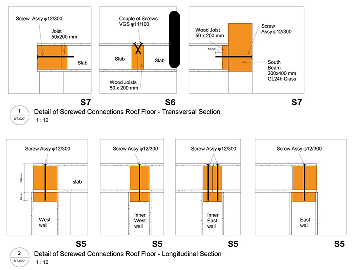
I chiodi vanno messi sul perimetro di ogni pannello (centrate nella parte strutturale della parete o del solaio) e in corrispondenza delle travi. Le viti che vengono messe normalmente si chiamano “viti assi” (screws wurth assy). Quando in un solaio la congiunzione tra due pannelli avviene in un punto dove non passa la di trave di fondazione è necessario l’uso delle viti incrociate (couple of screws rotho blaas).
The nails should be placed on the perimeter of each panel (centered in the structural part of the wall or floor) and in correspondence of the beams. The screws that are placed normally call "screw wurth assy". When the junction between two panels is in a point where there is no corresponding foundation beam requires the use of a “couple of screws rotho blaas”.

Le verifiche strutturali tendono a modificare la dimensione dei pezzi di solaio, quindi serviva una procedura automatizzata che velocizzasse il disegno dei relativi elaborati al cambiare del progetto.
The structural tests tend to change the size of the floor and wall slabs, and so it was useful an automated procedure that speed up the design of the sheets at the change of the structural project.
Per questo ho scelto di utilizzare Grasshopper per Rhinoceros, nel disegno in Autocad dei muri e dei pezzi di solaio ho disegnato solo gli assi che dovevano ospitare la cambrettatura.
For this reason I chose to use Grasshopper for Rhinoceros, in Autocad I drew only the axes’s hosts of the nailing of walls and floor pieces.
CAMBRETTATURA SOLAI - FLOOR SLABS NAILING
viti assi - screws wurth assy
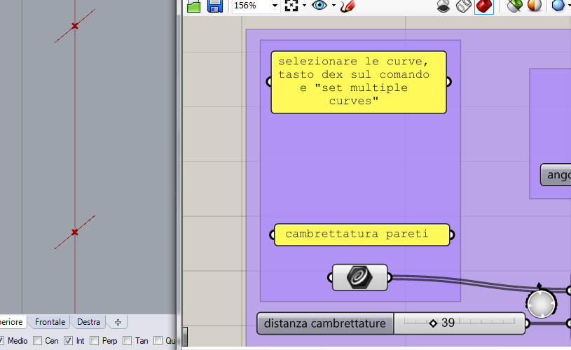
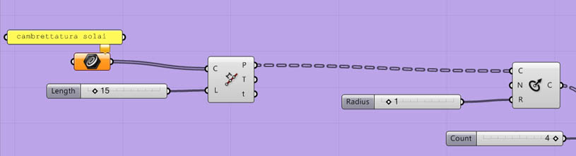
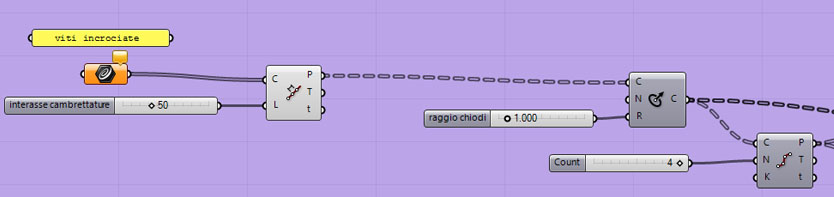
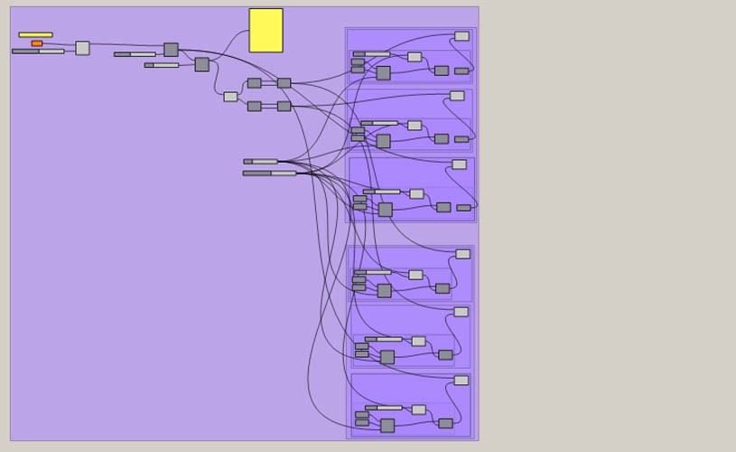
Ora avendo il disegno delle linee di asse della cambrettatura, che ho precedentemente raggruppato in layer (uno per le viti assi e uno per le viti incrociate) le seleziono, vado su Grasshopper e con il tasto destro>SET MULTIPLE CURVES. Poi suddivido ognuna di esse (devono essere linee esplose, non concatenate) per lunghezza (quella che necessita da calcolo) e ad ogni punto di suddivisione risultante applico una circonferenza di raggio 1.
Now having the drawing of the lines of the nailing’s axis, which I previously grouped in layers (“screw wurth assy” and “couple of screws rotho blaas”) I select them, I go to Grasshopper, Right Click > SET MULTIPLE CURVES. Then I split each of them (lines must be exploded, not concatenated) to length (one that requires calculation) and at each point of division I apply a circle of radius 1.
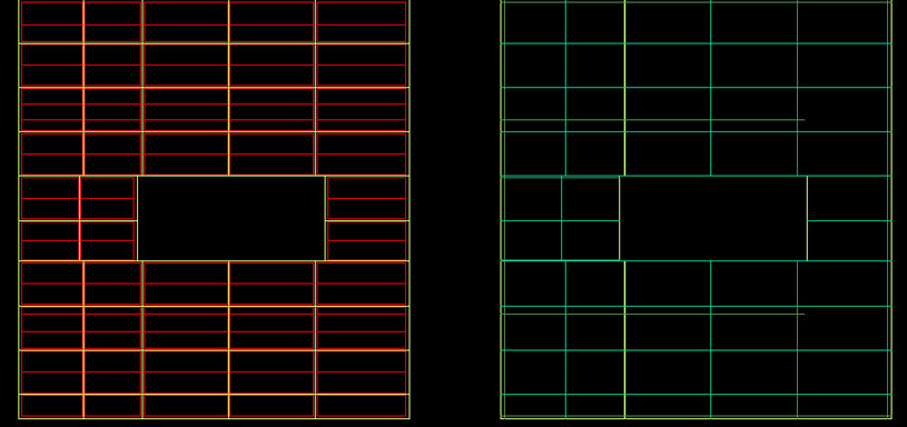
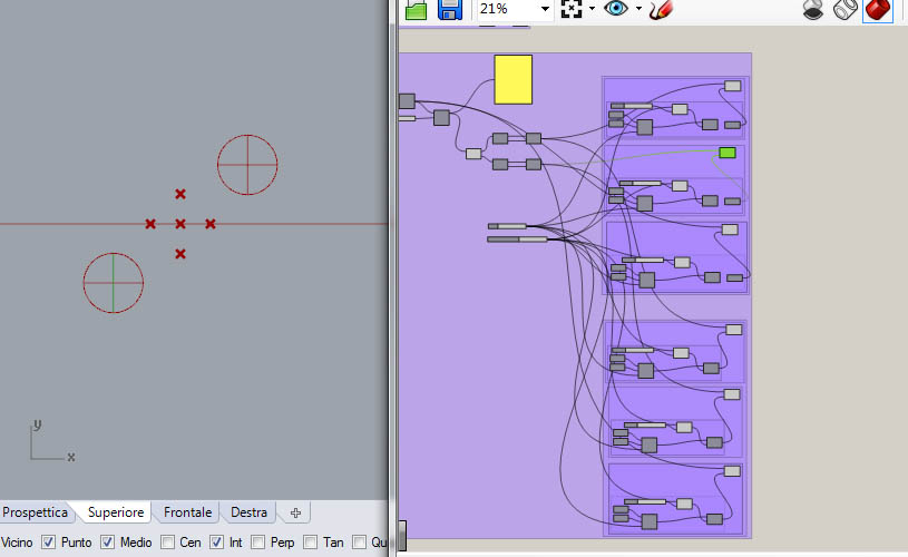
ESEMPIO: in giallo è rappresentato il perimetro di ogni elemento di solaio, in rosso gli assi dove si impostano le viti assi (le viti assi sono messe in corrispondenza degli elementi strutturali del platform frame, quindi in corrispondenza dei travetti di solaio o delle travi)
EXAMPLE: the yellow lines are the perimeter of each floor slab, in red the axes where you set screw wurth assy (the screw wurth assy are placed in correspondence of the structural elements of the platform frame, and then at the floor joists or beams)
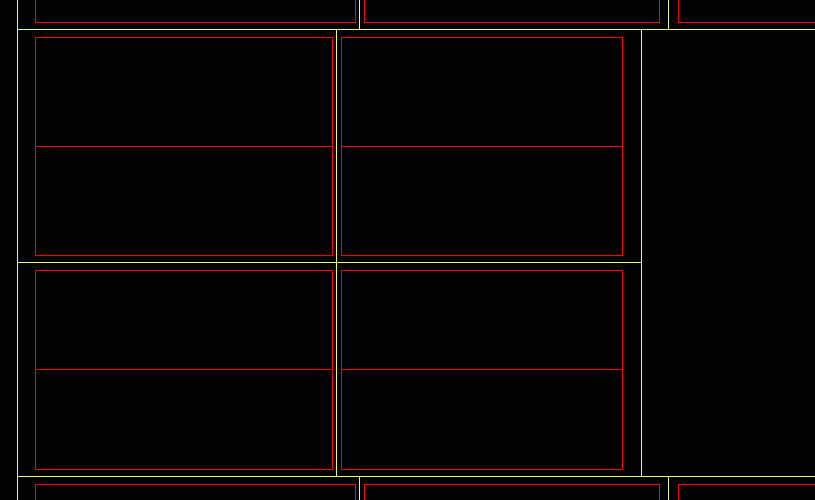
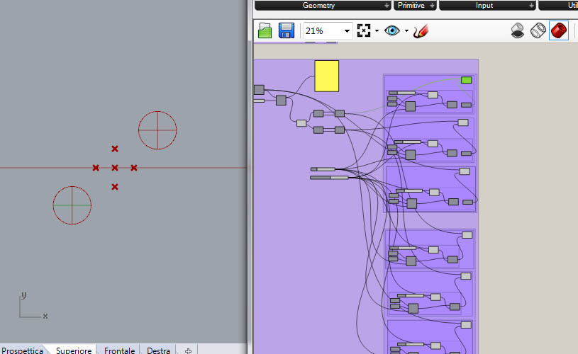
Sul lato destro invece sullo stesso solaio sono rappresentate le viti incrociate in color ciano, le quali vengono poste al perimetro di ogni pannello in assenza di travi sottostanti. In verde invece sono rappresentate le linee delle viti assi che passano in corrispondenza delle travi, quindi viti assi dalla profondità maggiore.
On the right side on the same slab are represented “couple of screws rotho blaas” in color cyan, which are placed at the perimeter of each panel in absence of underlying beams. Instead are represented in green lines the axes of the “screw wurth assy” that passes in correspondence of the beams, and then those are “screw wurth assy” that needs greater depth.


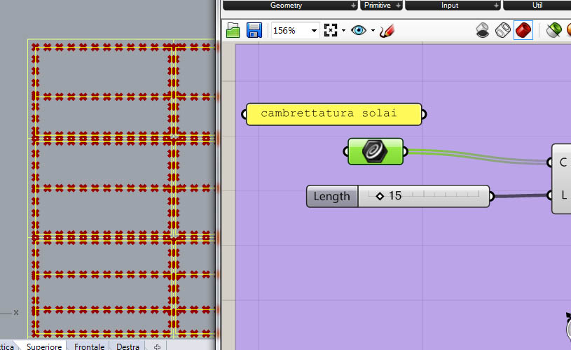
Qui vario la lunghezza della suddivisione e quindi anche la distanza fra i chiodi
Here I have varied the length of the subdivision and therefore also the distance between the nails
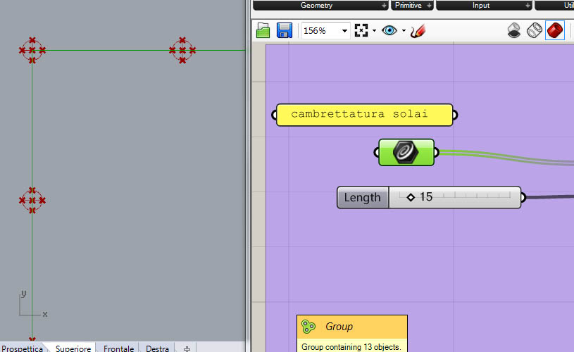

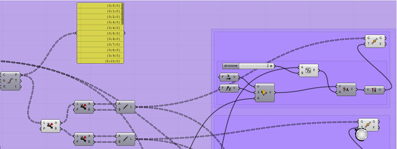
Suddivido ogni cerchio in 4 punti e li seleziono alternati in modo da poter unire i due punti opposti della circonferenza con una linea (queste linee servono per la rappresentazione convenzionale delle chiodature)
I split each circle in 4 points and I select them alternately in order to connect the two opposite points of the circumference with a line (these lines are used for the conventional representation of the nailings)


CAMBRETTATURA SOLAI - FLOOR SLABS NAILING
viti incrociate - couple of screws rotho blaas
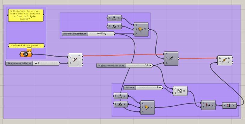
Ho usato lo stesso procedimento anche per la parte iniziale della modellazione in Grasshopper delle viti assi...
I used the same procedure as for the initial part of modeling in Grasshopper screw axes ...
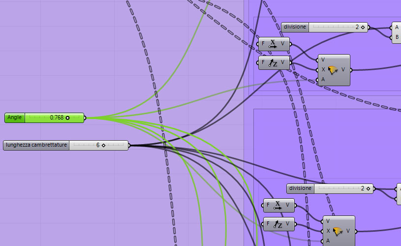
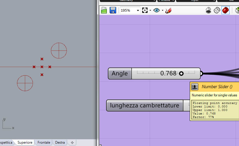
...con la differenza che adesso quei cerchi e quelle linee vanno rototraslate e specchiate specularmente due volte: per fare questo ho usato un vettore generico in direzione X e l’ho ruotato con attorno a Z di un angolo per determinare la rotazione.
... with the difference that now those circles and those lines have to be rototraslate and mirrored specularly twice: to do this I used a generic vector in the X direction and I rotated it around Z by an angle to set the rotation.
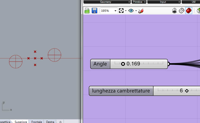
Questo procedimento l’ho dovuto ripetere per la linea orizzontale…
I had to repeat this process for the horizontal line ...
...per quella verticale..
...for the vertical one..
...e per la circonferenza.
...and for the circumference.

Il tutto ripetuto due volte per fare l’altro chiodo
All repeated twice to make the other nail
CAMBRETTATURA PARETI - WALLS NAILING
spillatura - stapler nailing
Il procedimento qui è più semplice: si deve solo creare una linea inclinata il cui centro è il punto che suddivide la linea d’asse.
The process here is simple: you just have to create a sloping line whose center is the point that divides the axis line.