XLAM_"house-of-cards" pavillion

In this series of post Giulia Settimi, Valerio Socciarelli and Me we're going to explain and develop design process of a wooden pavillion project made for a tecnology workshop here at Roma3 together with Giuliana Mosca.
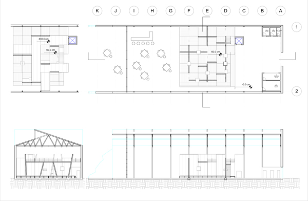
We had to design a small 300sqm pavillion within an existing structure (an 900sqm hangar). Since hangar's space is already defined and measured by its inner structure we wanted to add a form capable of playing with existing module, in order to create a movement in the space.

Thus we tought about House-of-cards.The idea came from a material whose name is XLAM: it's a wooden laminated timber, made of solid panels glued together in a cross order. Panels module is half distance between existing truss (measure produced by fabricator).
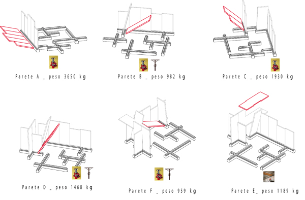
Xlam is a load-bearing material. Structural concept is based on dihedral angle stiffness: three ortogonal planes fit in together create a solid stiff structure, stroger than the sum single elements , if connexions are good enough.

Starting from fabricator's data availale on the net, we draw nodes and situations for our structure, after getting into proportion using rough data available on website. We made a little bit of detailing design as well (with regard to xlam panels connections, for instance). 1:10 nodes only are not drawn in Revit
Since we've been using revit, weve been able to design, schedule and communicate significative aspects of this new-tecnology based project, such as
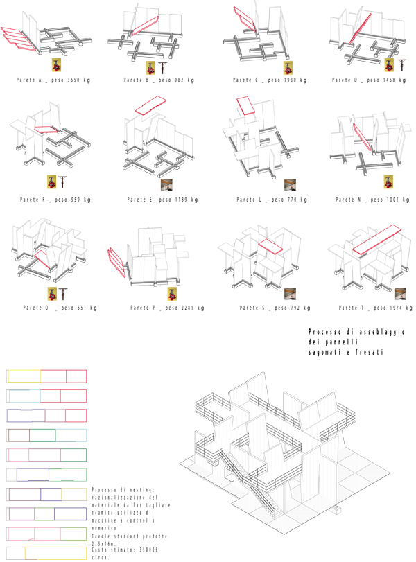
- assembly order: we tried and make a constructive simulation, pointing out each panel's weigth and tools necessary at each passage
- fabrication data: we are working on panel-fabricated material, so we provided a nesting hypotesis
- material cost: about 35.000€ (xlam costs 500 €/cu m)
Due to timing, we explored xlam related part of this project only.
Besides re-thinking and completing the whole project, what we intend to do is:
- performing a structural analisys in order to obtain and verify form; in particular understanding joint's role/nature and determining how thick panels shall be
- making a total bim model of the new design in group
- producing data such as costs, drawings, fabrication data and constructive data
- producing an assembly simulation, verifying role of time over the construction yard.
Commenti
StefanoConverso
Mer, 27/01/2010 - 12:22
Collegamento permanente
Masses as reference geometry for intersecting panels
Dear group,
I went through yoru problem of working with masses
and then having wall panels attached to them update
and being cut according to mass intersections.
I think your idea of building up a "mass model" of your
pavilion works great, since masses can be easily updated.
The trick I've found is that you have to use voids in order
to cut masses, and that can be annoying. That is, though,
the only way to do that.
Each mass can have its own void cutting it.
This model down below is a solid+void cutting it.
Walls are attached to it and update
You can edit the form at once, though, with the arrows:
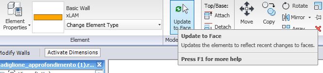
Then ... to update the model
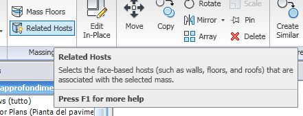
you can - select the mass... click on highlight related hosts
and then update to face:
1.
2.
I had a little problem with your levels and offsets.
Maje sure mass and objects are built on the same level
(or work plane), to avoid offset problems.
So given that you know more or less you intersections,
you can "embed" them into your panel masses.
OR, you can have a 1-mass model that is then
all one thing (which is a little tricky).
Does this help you?
To be honest, it would be great to find a
"panel-related" solution, which seems more
to be your way, but this comes with using
facade systems, I suppose.
So masses are not the actual panels,
but just reference geometry for curtain walls.
I think showing pictures of the XLAM
material that you are using might help.
Stefano