Tu sei qui
Part 2: Construction of facade
Panel that I wanted to create with using a formula for sinα didn’t worked, so I left it for later to create another part of my elevation - a steal frame. As in the existing building of Cloud 9 I wanted to use the same triangle form for elevation construction.
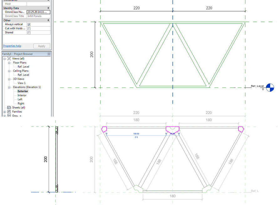
I started with half of a plaster of honey, thinking is the best complex model. I was fallowing the process of creation, it came out that for each beam it’s better to make other families for metal connectors, and then paste it to Metric Curtain Wall Panel, locking it with every possible way, to the references lines or one to another.
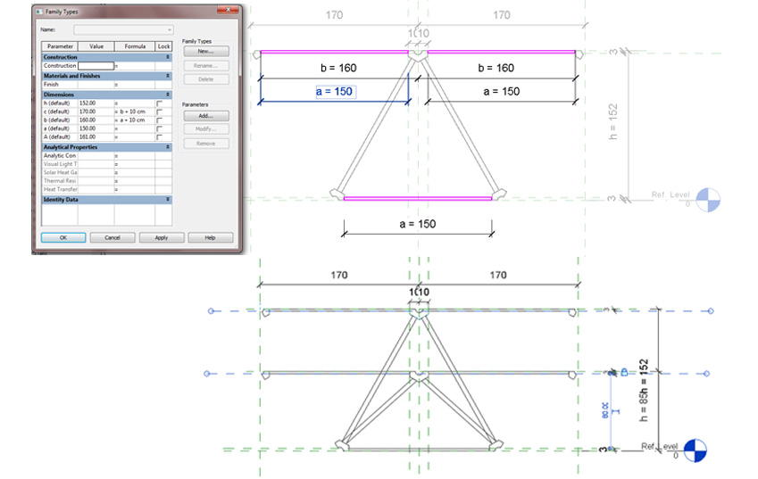
I added constant element to wall panel- the connections between beams. However it came out that I can load them into the project of grate and connect with beams, but it was working only in horizontal direction not vertical. I tried to solve it by combining with a parameter of high - ‘h’ - and it worked. In the elevation file on the left bar (in a family of steel connectors) I added parameter of offset = ‘h’. The same as for the high of the grate, but only for the top connector, because the position of low part doesn’t change.
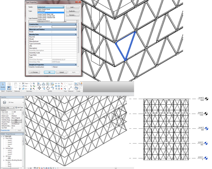
Then another problem appeared. It was very difficult to create another cross beams, connected with reference lines and the rest of the construction, and to make it work in each working space. It wasn’t only a problem of reference lines, so I decided to simplify the model to a triangle.
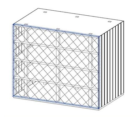
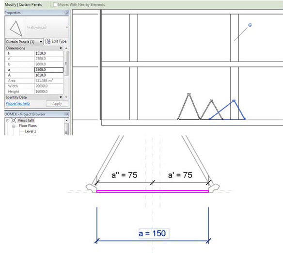
I did a model of a building with elevation on which I wanted to put all the elements of a facade. On it I could also check how grate works, and what to change to make it work. For ex. the symmetry of grate wan’t working, because of lack of parameters defining changes in the structure.
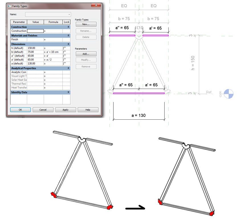
Only triangle wasn’t enough, so I added half of a beam on the upper side and change the steel connectors (in their families changing the shape). Acctualy I created 2 families with this connectors, one half of a hexagon, another one ¼ of a block. On the picture the red part of connectors that I had to change. I added also extra parameters which are necessary to define the changes in the grate.
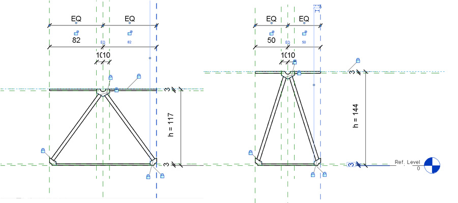
Pictures showing how references lines work, and how I load it to the project of a building. Last part left is the red area, on the elevation. It is a part on which I have to create the same grate but in a mirror view, to make this beam look like the shape I wanted to fallow.
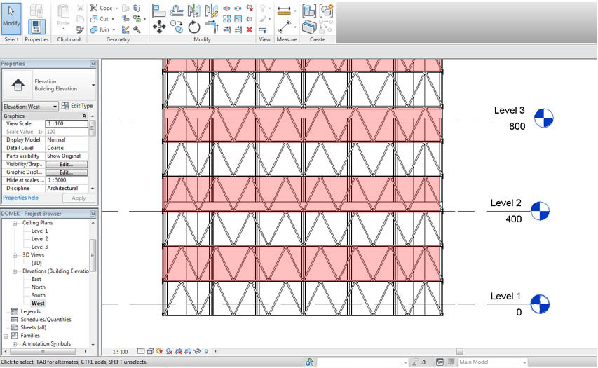
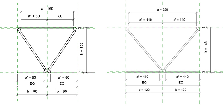
Upper, is a second panel, mirror of the previous one The idea of creating it was similar, only difrent steal connectors has to be locked. In that case doing a mirror view is imposible, whole the model has to be constructed from the beginning. Then I load it into the project, as the red line suggested replaced panels. Now the compilation has changed. We can also change separetly each part of an elevation. Not only by elements, but also by changing axis and widness of separate units.
Another changes to do is to make complete beams, and connectors, to later put them in the schedule of elevation. Last part is to connect this steel construction with elevation cushion, as a decoration and functional aspect of a project of Cloud 9, Media-TIC – office building in Barcelona.
| Allegato | Dimensione |
|---|---|
| 468 KB | |
| 580 KB |
