Tesi master theses
Devoto fabrication partner
CNC: real experiences | case studies
Acoustics projects | form | analisys
Custom Families Revit
Data Production model to data
Visual Basic scripting for Revit
Barrisol project for a conferece hall
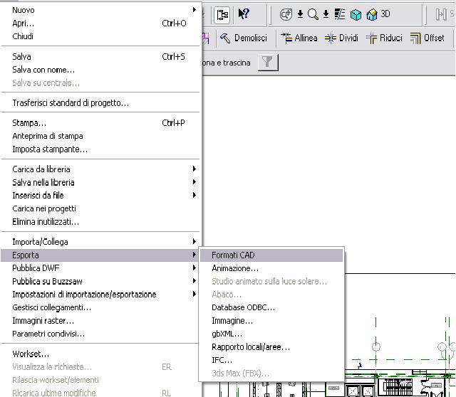
Ecco una brevissima guida su come esportare i file dwg da revit con dei layers che abbiano nomi riconoscibili.
Per prima cosa bisogna andare dal menu file in esporta
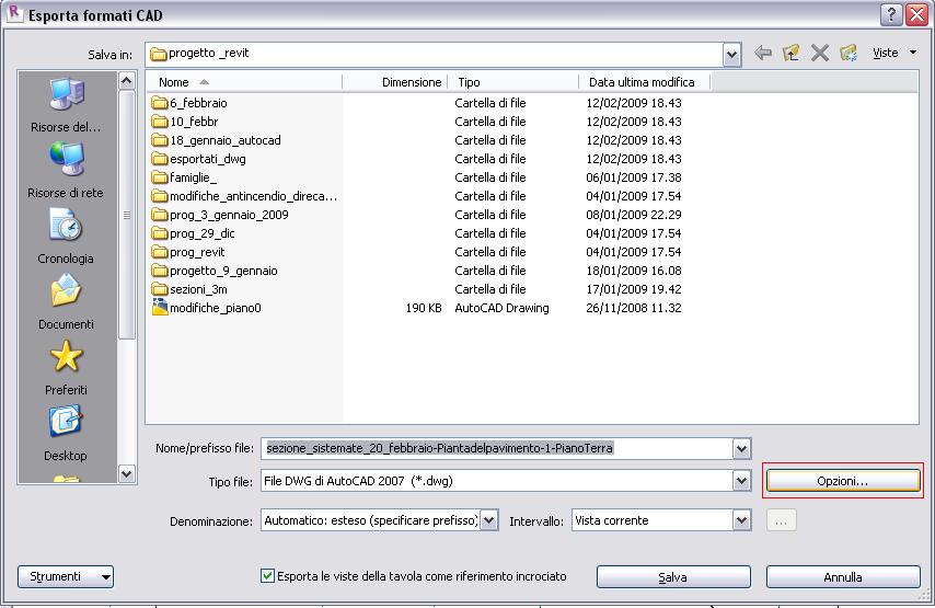
poi in opzioni,
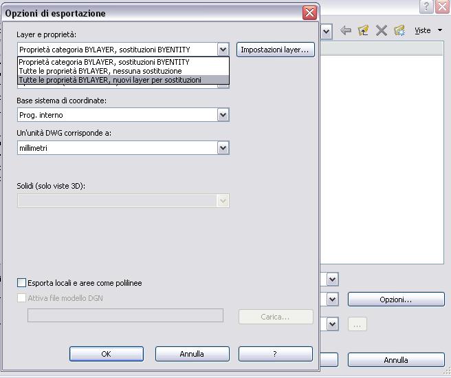
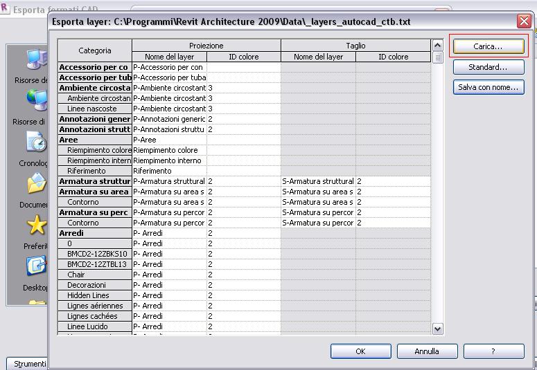
e settere le proprietà di esportazione quali scala o sostituzioni layers
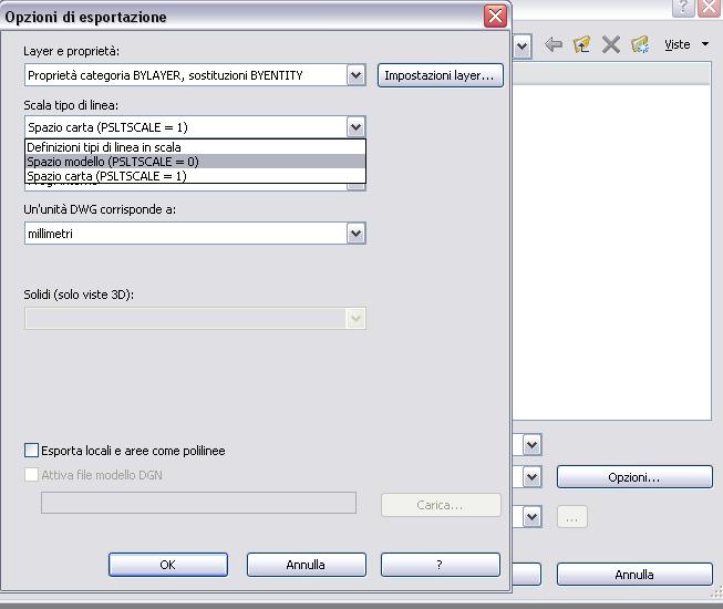

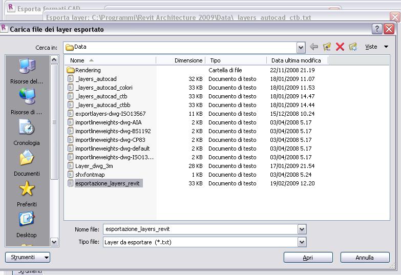
e per ultimo andare in impostazione layers e caricare il file txt, in cui sono riporatti tutti i nomi di tutti i layers che compariranno in autocad che allego. Premetto che non si può pretendere di avere in autocad il file perfetto per la stampa, bisognerà lavorare un pò sui layers spegnerne alcuni e modificare il ctb a proprio piacimento
dopo aver caricato il file txt il gioco è fatto, basta caricare il file ctb in autocad, per chi non lo sapesse

caricare il file nella cartella dei stili di stampa di autocad e il gioco è fatto!

N.B.
per poter scaricare i due file allegati (TXT e CTB) è necessario prima effettuare il login nel sito!
Attachments are available to registered users only.
| Allegato | Dimensione |
|---|---|
| 32.53 KB | |
| 4.68 KB |
commenti
jandes
6 Marzo, 2009 - 10:02
Collegamento permanente
templates
Ciao,
non riesco a trovale gli allegati, da dove posso scaricare i due files (TXT e CTB)?
grazie
gademic
6 Marzo, 2009 - 13:36
Collegamento permanente
Esportazione dwg da revit
Si è vero chiedo scusa,
il file txt sono riuscito a ricaricarlo, quello ctb mi dice che non lo posso caricare sul sito...
Stefano hai tu una soluzione per mettere a disposizione di tutti il ctb, il ctb lo avevo copiato nel tuo pc il giorno dell'esame...
a presto,
gabriele
admin
6 Marzo, 2009 - 15:39
Collegamento permanente
ora anche il ctb
sistemato, ora c'è anche il CTB
StefanoConverso
6 Marzo, 2009 - 15:28
Collegamento permanente
il txt lo trovi allegato
caro Jandes,
benvenuto sul sito,
trovi il file TXT per l'esportazione dei layer da Revit
allegato al messaggio. Abbiamo chiesto a Gabriele anche
il relativo CTB da lui usato, speriamo lo faccia presto.
saluti,
Stefano
StefanoConverso
7 Marzo, 2009 - 14:26
Collegamento permanente
Importare DWG in Revit: attenzione alle coordinate
Cari tutti,
vi sottopongo un interessante link legato al tema import/export DWG in Revit:
http://revitclinic.typepad.com/my_weblog/2009/01/the-2-mile-barrier.html
Da Revit Clinic: non lavorate mai lontano dall'origine!
Revit non dà automaticamente notizia delle coordinate degli oggetti: ad ogni modo, in un nuvo file, l'origine è in genere dove si incrociano i segni delle viste e dei prospetti (quindi, se li vedete lontani in seguito a qualche importazione/ricalco di file...potreste essere lontani dall'origine, e se è troppo lontano, Revit può andare "in bambola" a quanto dice questo blog (13 zoom out e siete lontani due miglia!).
Se vi capita, per sapere dov'è l'origine, un trucco potrebbe essere importare un file AutoCad con l'opzione
"origine a origine", in modo da trovarla subito, dice sempre l'autore, Harlan Brumm: Thanks Harlan!
La sorgente indicata anche da lui è ovviamente AUGI:
Revit Origin and Shared Coordinates:
The Project Coordinates origin can't be moved. This is not a problem unless you have more than one coordinate system that you need to work with on your project. When the project only needs one 0,0 point, you can locate Shared Coordinates to align with the coordinates in question (Revit is more cooperative in this regard than it was in the past).
Now: you need to know that Revit ignores the BASE command in AutoCAD and assumes that 0,0 is the origin. Here's the deal: import a 100' circle with a 150' line from 0,0 going straight up drawn in AutoCAD with center 0,0 with the origin-to-origin option into Revit. The center of the circle will give you the Project Coordinates origin for your Revit project. This origin cannot be moved or altered; it's just there. I get users to put this into all their office templates so they know where this is and can use it effectively.
Now draw a (exactly) 5280' circle around the Project Coordinates origin. If the insertion point of the DWG (remembering that Revit assumes 0,0 in Acad is the origin) is such so that the whole DWG fits inside this circle, you're good. Otherwise, you're manually moving DWGs into place. So Revit works fine, provided the DWGs fit inside this 2-mile-wide circle. Revit objects can be outside this circle without affecting the insertion of DWGs.
An upshot of this: if the Shared Coordinates origin and the Project Coordinates origins are more than 2 miles apart, importing by Shared Coordinates always fails -- it defaults to center-to-center. So if your DWG is a mile wide and 0,0 is in the middle of it, the Shared Coordinates origin must be less than 1.5 miles from the Project Coordinates origin for import by Shared Coordinates to work seamlessly.
---
Here's David Conant's additional information about Shared Coordinates in Revit. Despite what David says about Revit not liking large coordinates, Revit has floating point precision, but limitations in Window's display system forces the Factory to impose some guidelines, which are discussed here:Factory says: This is one place where you have to follow the rules.
Revit's internal calculations do not like very large coordinate numbers. There are many number systems used in an app like Revit, some for calculating values, some for driving the display, etc. In some cases these systems differ in the precision of the numbers they can use. When numeric values are small, these differences in precision are insignificant. When numbers get large, the differences while still small on a percentage basis become large enough to effect the reults of display and operations. Thus, it is important to keep your Revit project near Revit's origin. (near means within 1 mile/1.6km) Revit's origin is near the center of the space made by the elevation symbols in the default template.
The Rules
Always build your building near the starting point of the default template.
Model it with Project North pointing directly up. (lay it out as you would have it appear on sheets)
If you are using a dwg based site, Link your site file Center To Center.
Move or rotate the SITE under your project until it is correctly positioned relative to the building. (do not move or rotate the project itself).
Use the Acquire Coordinates tool and pick the site.
This will set your project's shared coordinated to those of the dwg's wcs. True North will be the dwg's Y axis. Now your building knows where the dwg 0,0 is, but it can still record its own information in well behaving small numbers. It knows and can orient to either True North, or Project North. Once the shared coordinates are set, subsequent imports can be made origin to origin using shared coordinates.
http://forums.augi.com/showthread.php?p=718797
a presto,
Stefano
p.s.
Postate altri commenti/link in materia!