Tesi master theses
Devoto fabrication partner
CNC: real experiences | case studies
Acoustics projects | form | analisys
Custom Families Revit
Data Production model to data
Visual Basic scripting for Revit
Barrisol project for a conferece hall

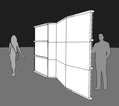
After the last post I tried to put my thoughts into a model. I did a first model that helped me to understand what kind of problem I could find in this step from paper to screen.
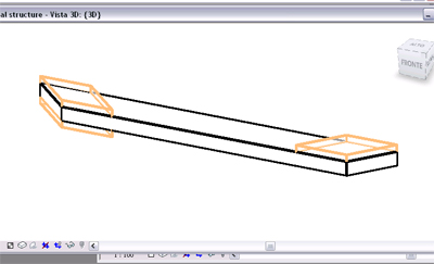
1_HorizontalStructure:
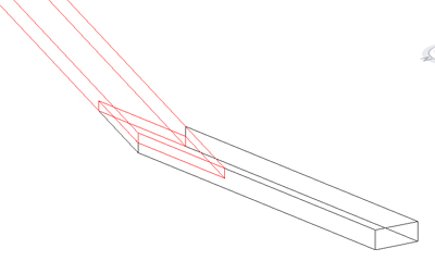
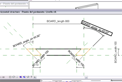
First theme to face was the definition of orizzontal structure. This is made of board and the problem was to design the nodes where two elements joint together with different angles. The node works with the final section of the board that is rotated following the side of the other board (watch the following screenshot).
The problem was the definition of parameters, this is related with necessary variation in the shape of elements:
- rotation of end section;
- control of board length and width;
- position of joint teeth and of joint width in order to make possible the jointure.
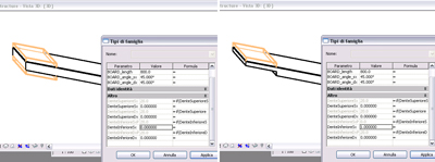
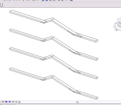
The parameter that was harder to controll was the one about the position of the teeth. I got different type of board (the one at the beginning for example has not tooth on its start, the ones in the middle have teeth on each side) and I wanted to design just one family in order to work with this and different types.
I drew different parameters for: board length, board width and for the two angles of top and bottom sections.
To draw the teeth I design 3 different void volumes (3 and not 4 because on one side I just need a single variation, it will be easy to understand looking the final model), those are related with an height parameter that lead them to be in or out of the solid volume of the board. In this way I can chose if I want to have the tooth in the left or/and right and and in the top or/and bottom side of the section.
Those volumes are lincked with the same angle of the master board, but I realized that when I have the rotation, the two sides of the cut don't keep the original width. In order to eliminate this problem I put the board width parameter (the same one that lead the short dimension of the board) also to lead the cut dimension (I did it because if the cut dimension changes, it would not be able to joint with the other board).
The result is a structure made of 4 different floors: first 3 are equal, the last one is wider because I wanted it to work as close line in the elevation of the showcase.
2_Panels:
Panels design toke start always from the thoughts of last post. First problem was if it would be better to have one-piece panels (from bottom to top) or different panels that link the structure floor to floor jointed one with the other. I finally chose to have different panels. This choice was related to carrying of the elements but also to elevation aspect (I'd like to have all the lines of the panels jointure that follow the structure bend).
I have different type of jointure, they depends from what kind of elements they joint.
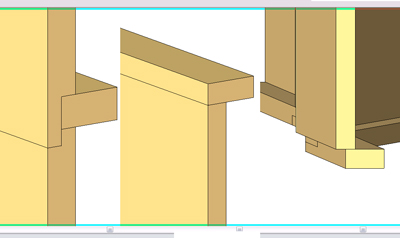
Left: middle node between the two panels and the orizzontal structure.
Center: top node. Here I want the panel to end on the orizzontal structure (that is 2 cm wider of the others) in order to have a double line that underline me the top end.
Right: bottom node, the structure is 2 cm back of the panel finiture, this is to create a small shadow on the bottom of the showcase.
Working on the panels I would like to have just one family but I had problems and I finally had 3 different families, each one work for one level of the structure (bottom panels, center panels and top panels).
The panel as family has parameter for length height and angles, the tooth is fixed on the side I ned.
Panels follow the front side of the structure on its first 3 modules, on the last one they are on the back side so showing the orizzontal elements running behind. I also put some vertical (metal?) frames that link the orizzontal structure together but their function more than structural is formal (the could be some rotation points, but I remember that the structure is fixed, not customizable from users).
commenti
StefanoConverso
2 Febbraio, 2009 - 18:46
Collegamento permanente
The variations?
Tommaso,
I see that there's a clarification in your intent.
The "folding" of your panel seems now to be a clear topic for your work. In particular, the images of the horizontal structure show the possibility to make the joints have an aesthetic quality.
I wonder how is this quality related with the flat panels? The structure seems asimmetrical, which is also good, but this relation must still explored, I think.
Maybe the panels are not vertical but oriented to the sight?
As usual, I suggest you to explore and post variations.
And finally, can you add some more words on the possibile construction system to be used?
TommasoBerretta
2 Febbraio, 2009 - 19:14
Collegamento permanente
_ _ _ _ _ _ _ _ _
I guess could be interesting to variate the panel orientation in order to make it related with user point of view. What I don't know if it's possible just orientating the panel or I could take the back side perpendicular with the structure and the work by "eating" the other side and giving it a slope in order to have an orientation.. In this sense the problem could be the waste of material (maybe I need to glue 2 panels to have a bigger thickness).
What do you mean for construction system?
StefanoConverso
3 Febbraio, 2009 - 19:18
Collegamento permanente
milling the panels
Tommaso,
what I was suggesting is to mill the panels in order to have a lighter and more vibrant structure.
As for construction, I mean mostly the joints: glued?
Last:is the wall self-supporting?