Tesi master theses
Devoto fabrication partner
CNC: real experiences | case studies
Acoustics projects | form | analisys
Custom Families Revit
Data Production model to data
Visual Basic scripting for Revit
Barrisol project for a conferece hall
.jpg)
Last week i've been fabricating a prototype of my component at Devoto's.
What we've made is the diffusive part of it: we succeded in assemblying two modules, while the other four plus a very rough sitting will be fabricated next week. Starting from data i've produced (see last posts), process has involved these steps:
1_fabrication data
.jpg)
I went at Devoto's with: a 3d model, exportable in STL file; part schedule; a nesting hypotesys. What we need to fabricate is a real-scale Schroeder diffusive module for acoustic tests. Fabrication department let me understand soon that this material was not enough for initiating the process, though everything could have been sorted out of it.
STL file cannot be processed by 3-axis CNC milling machinery (i mean: Devoto's CNC dealer is not used to do so). They use a software whose name is Alfacam: it accept both NC anc CAD geometry as imput.
Cad file shan't be a "photography" of what we want to fabricate: thus because milling is a far more "sculptural" process, we're talking about subtracting matter. Therefore, the standard imput for Alfacam is a file containing milling paths.Producing this kind of cad geometry implies a certain knowledge of both machinery and material, as we are about to discover.

First file we've produced was this one above. Green and MAgenta paths are tought for different tools (different mills). The only information geometry itself contains is kind of path: whether it is tool's center (magenta: 4mm mill) or border (green: 20mm mill). However, importing process it far from being automatic, so paths we're drawing shall be "described" to Alfacam, as we'll se after.
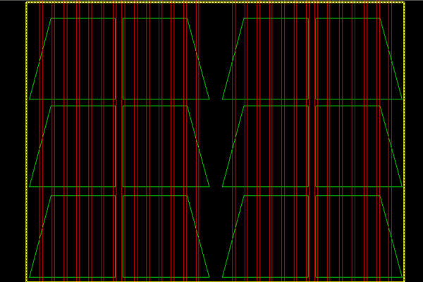
We've soon discovered that Devoto's 4mm mill was out of use...so we'd had to use a rotating saw. In the new file, red signs are blade center paths.
It's important to draw geometry thinking about tools: for instance, if we want to carry 4mm +0.2mm (tolerance measure) channels out of the wooden slab, we'll need to draw two lines whose distance is 1mm: thus because blade width is 32mm, and so passing twice at a millimeter distance we'll reach desired width. Furthermore, changing mill into a rotating saw obliges us to make all-panel-long channels: thus because saw radius is 12cm!
So we need to find out another way of "tracing" dividers position, even if mr Devoto states it is not necessary (and so very first prototyipes won't have it).
.jpg)
Importing CAD geometry into Alphacam is a procedure which should be explored deeper, according to me. At present, we're able just to import paths only, not even layers.
Colours play a fixed role in AlfaCam: working board, contruction lines, geometries, tool paths, other tool paths and so on.
.jpg)
First thing we do is defining the board: besides specifying measures, it is mandatory to say where the board will be fisically placed on CNC milling.
.jpg)
What we have now is a board: plase note that model orbits 3d, while our geometry is 2d (we'll se why later on).
.jpg)
After that, we shall import cad geometry...
.jpg)
...and place it onto the board. Please note colours.

It is possible to see and set starting points on each manifacturing path. In this step we specify wheter lines are centre or external paths.
It is better to put starting points not on vertex. Futhermore: cnc machine will read polylines or blocks as a single path, while sum of single lines means sum of different manufacturing actions.

Now it is possible to select a tool....

...and assign manufacturings to paths.
This step is crucial and implies a good amount of experience. Please note that besides the kind of manufacturing we decide: manifacture depth, curve radius (if different from tools' ones), number of coatings and ALL z-axis reference quotes.
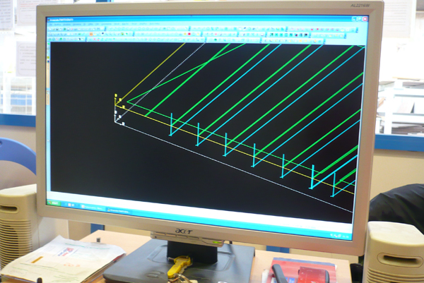
It is possible to visualize paths in 3 dimensions, but software does not give a solid prediction of finished work.
.jpg)
In this visualization we see "coating" number: for instance, milling machine won't define cut panels of the board in a sigle manifacture. Please note that all paths have the same colour: which mean that they will be executed by same tool, while we obviously do not want to.
.jpg)
Besides printing -as a normal cad programm does-, the real output given by AlphaCam is a preparatory code: the one CNC machine is able to read.
Please note that:

Postprocessor shows the finished results (manifacture paths): each path as a number, which corresponds to IDline(s).
2_cnc machinery at work
.jpg)
As i've already said, machine dealers are able to read and modify this code directly into machine's computer.
.jpg)
They are used to check errors, and correct parameters. Obviusely, they cant' write bit of code by themselves, so when a program is wrong, Alphacam dealer ought to redo it properly (I had to as well).
.jpg)
A couple of important things to do aside machine computer rather than on AlfaCam.
1_selecting what geometry to pantograph. If this is a first time pantographing, it's indeed better to make a try, so dealers can select which part of code executing and which ones not. They're used to use scraps for this process.
2_ they plug tools in and assing their proper number into the preparatory code. MAchine change tool by itself.
.jpg)
The milling machine has a board which sucks air in: so panels are like glued to machine workplane. It is important to set RefZQuotes properly, in order not to ruin workplane, but humans often make mistakes.
.jpg)
Underneath the board we want to pantograph we need to put a so-called "martyr board": name says all.
.jpg)
An important procedure is alligning -mecanically- work board.
.jpg)
Preparatory code already knows we're going to work low left work plane area.
.jpg)
Panel is ready to be pantographed...
3_other parts
.jpg)
.jpg)
We still need to fabricate dividers and lamelle, but this is far easier since they just need to be cutted.
.jpg)
What i do is writing manually a schedule. I have exported measures and quantities via Revit, and after that i've given a new check after prototype base is ready.
.jpg)
Cutter machine can read these measeure as imput; furthermore we set cutting distances...
.jpg)
...and this machine provides nesting autonomously.
.jpg)
Just insert panels...
.jpg)
...and get other parts. Please note that this cutter cuts one direction at a time, so nesting is useful in order to hear "dealer- insert this part here, please" from the machine.
4_improving fabrication results
After this very first prototype, i've tried and improve the design, working directly on cad geometry to be imported in Alfacam.
.jpg)
First i've drawn paths for dividers' pits. According me these are useful to mark positions without making carpenter measure continuosly. These paths are centre tool ones, for a 6mm mill (so each angle should have a 3mm curve radius, but in this case curve angles are straightened by circular blade matter subtraction).
.jpg)
Exporting process shows this new design element...
.jpg)
...and the result is pretty good! We made this try on MDF panel, so the only mistake we can see is a mistake in pits' path, which is 0.1mm out of channel. But in very truth, there are two far more impressive mistakes, that we'll discover later.
.jpg)
What i do is drawing pits profiles to be emptied out: i notice this action just now.
.jpg)
FIRST MASSIVE MISTAKE. Please note that the program executes channels before mill manufactures.
.jpg)
And this is the final result...pretty bad.
Mr. devoto explained me that the problem is that in the program i've ordered to make channels before mill manufactures. Since we're working now with a grained wood (MDF is chipboard), this makes it break because rotating mill exfoliates wood, since it is weakened by channels!
Mr. Devoto was angry against people (me) who had made this program, because nobody could have made this very stupid mistake. I did: i had no knowledge about CNC machines before, and futhermore, i had not this kind of knowledges about wood.
This lead us to a key theme: how much can the architect do in order to simplify fabricator's work and save time?
It is my opinion that providing real fabrication data such as manifacturing paths (the maximum we can give) mean a really high responsability acceptance, which can be easily disappointed due to lack of knowledges on materials or machineries or tools.
A clearly undestandable geometry is already enough; while in order to export more is necessary to know directly machines, materials and people that are going to finish the process we started.
.jpg)
Please look at differences. Cad Geometry is the same, while just manifacturing order is changed.
.jpg)
This time result seem to be pretty good -while it is not exactly, we'll see-.
5_assembly
Now that every part is fabricated, we can start assemblying. At first, a couple of manually actions are necessary.
.gif)
Carpenter trim bases.
.gif)
And hand-fabricates special dividers (trapezoidal section). Milling these one would have been time costing and material expensive.
.jpg)
Carpenters states that adding pits in the design has been a good idea. Thus their work is more precise and faster.
.gif)
They assembly my component the same way i've described it on this site.
.jpg)
But sometimes tolerance measures aren't enough (just for the middle pits, which are coupled, so there is the need of a little extra artisanal work.
.jpg)
This is first Schroeder Diffusive module assemblied. Time: 45min, Weight: approx 20kg
6_constructive problems
Big issues occurred when assemblying second component.
.jpg)
As we clearly see, centre lamelle are visibly bended on the outside, so pits can't have the same width...this problem is annoying and unexpected, since lamelle e dividers are cutted into the same exact lenght.
.jpg)
Therefore, problem shall be the base. Indeed, if we have a closer look, we discover that a difference in channels' and pits' dig quote exists.
.jpg)
SECOND MASSIVE MISTAKE. Despite dig quotes are the same, we did not calibrate milling machine properly. Thus, a different in some tenth of millimeters on both sides create this annoying situation on the top of each component: since it is kept together via screwing dividers, lamelle, which appear to be longer, are bended aside because of base pression operated by screws.
.jpg)
Therefore, we need lot of extra work for correcting this mess...it is something that only caprtenter's hand work can do.
.jpg)
Problem is solved by gluing dividers and lamelle. In principle i wanted to manipulate them not so much, because lamelle shall be re-used in the real mockup as well. They succeded in gluing via tape, while it would be perhaps necessary to use silicone afterward.
.jpg)
Result: we assemblied 2 components and 1/3 in 2hours and a half...that's too much. We look forward completing these work on monday.
Ps: i like the frontal effect far more the lateral one
commenti
MarcoMondello
30 Settembre, 2009 - 09:41
Collegamento permanente
Six modules assembly
marco.mondello@gmail.com