Tesi master theses
Devoto fabrication partner
CNC: real experiences | case studies
Acoustics projects | form | analisys
Custom Families Revit
Data Production model to data
Visual Basic scripting for Revit
Barrisol project for a conferece hall
I'm goint to explain Elisa Conversano's work.
1_about the routine
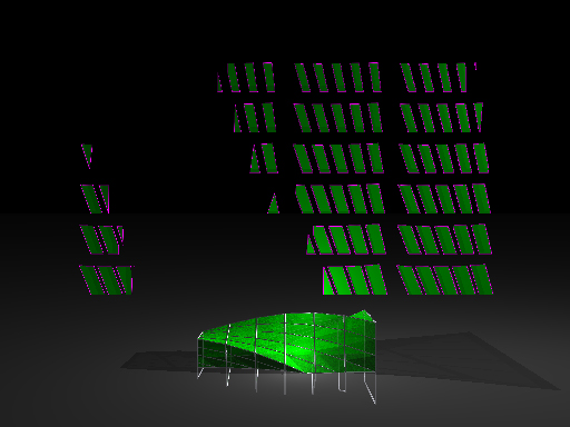
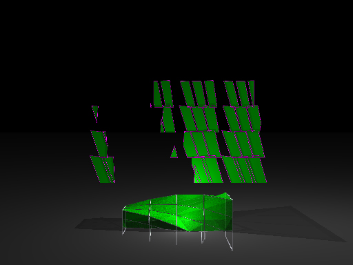
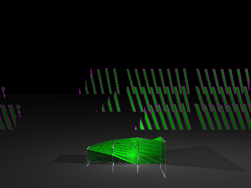
She produced a routine which is able to draw an approximation of the blankets in the project and, after that, unroll them in order to give the real (approximated) dimension.
In order to do so, she used a ray-tracing program whose name is Pov-Ray. This tool is useful, tough it does not produces a "solid" model, rather an image -.bmp-. It is somehow able to communicate with rhinoceros, but, at present, i have not succede in making it work like this. The whole routine contains several parameters.
The whole model has a problem of approximation. Indeed, it approximate a blanket as a number of couple-of-triangles which connect the four point on each side. This is due to the impossibility of a double negative curvature surface to be unrolled over a plane. The model is therefore divided into a number of strips, and elisa succeded in unrolling them using vector operations basically.
We still have to understand whether an high number of strips approximates the tense blanket propely.
2_routine
#include "colors.inc"
#include "textures.inc"
//---------------------------------------------------------
//
// as usual i set camera, lights, floor...
//
//---------------------------------------------------------
camera {
location <0,22,-90>
look_at <0,22,0>
angle 50
}
light_source { <3,10,-2> color 1 }
light_source { <40,40,-6> color 1 shadowless}
light_source { <2,3,-6> color 1 shadowless}
plane { y,0 pigment {Gray transmit 0.7}}
#macro Assi (Dir,Col)
cylinder {10*Dir,0 0.1 pigment{Col}}
cone {10*Dir, 0.3, 12*Dir, 0 pigment{Col}}
#end
//---------------------------------------------------------
//
// pavillion structure
//
//---------------------------------------------------------
// width (along the x-axis) of the pavillion
#declare Width = 25;
// pavillion's radius (that is the upright distance from the x axis)
// Radius0 referring to 1st upright; Radius1 to the last
#declare Radius0 = 4;
#declare Radius1 = 8;
// pavillion's heigth to the ground
#declare YPos = 1.2;
#declare N = 4; // NUMBER OF UPRIGHTS
// uprights' vertex
#declare Pts = array[N][4];
// uprights' positions
#declare I = 0;
#while(I<N)
#local T = I/(N-1);
#declare J = 0;
#while(J<4)
#local P = <(T-0.5)*Width, 0, (1-T)*Radius0+T*Radius1>;
#local Theta = 90*J - T*90 + 45; // (I,J)-th vertex's angular position (rounf the x-axis)
#declare Pts[I][J] = vrotate(P,Theta*x) + y*YPos;
#declare J=J+1;
#end
#declare I=I+1;
#end
//---------------------------------------------------------
//
// uprights drawing
//
//---------------------------------------------------------
union {
#local R = 0.1;
#declare I = 0;
#while(I<N)
#declare J = 0;
#while(J<4)
#local J1 = mod(J+1,4);
cylinder {Pts[I][J],Pts[I][J1],R}
sphere {Pts[I][J], R}
#declare J=J+1;
#end
#declare I=I+1;
#end
texture {Silver_Metal}
}
//---------------------------------------------------------
//
// Macro DrawPolygon(Pts)
//
// it draws a polygon by Pts points
//
// EdgeR = cilynder radius which represents the facets
// EdgeTexture = facets' texture
// FaceTexture = sides' texture
//
//---------------------------------------------------------
#macro DrawPolygon(Pts,EdgeR,EdgeTexture,FaceTexture)
// vertex number
#local M = dimension_size(Pts,1);
// drawing edges
union {
#local J=0;
#while(J<M)
sphere {Pts[J],EdgeR}
cylinder {Pts[J],Pts[mod(J+1,M)],EdgeR}
#local J=J+1;
#end
texture {EdgeTexture}
}
// drawing sides
mesh {
#local J=1;
#while(J+1<M)
triangle {Pts[0],Pts[J],Pts[J+1]}
#local J=J+1;
#end
texture {FaceTexture}
}
#end
//---------------------------------------------------------
//
// Macro Project(P0,P1,P2,Pts)
//
// it projects Pts[] polygon on xy plane in a way that
// P0 => origin, P1 => X-axis point, P2 => point of the XY plane
//
//---------------------------------------------------------
#macro Project(P0,P1,P2,Pts)
// vertex number
#local M = dimension_size(Pts,1);
// E0,E1 are the first two orthogonal vectors (whose lenght is 1)
// referring to the system whose origin is
// and P1 belonging to the 1st axis
#local E0 = vnormalize(P1-P0);
#local E1 = (P2-P0);
#local E1 = vnormalize(E1-E0*vdot(E0,E1)); // orthogonalizing
// results published in Q[]
#local Q = array[M];
#local J=0;
#while(J<M)
#local P = Pts[J]-P0;
#local Q[J] = <vdot(P,E0),vdot(P,E1),0>;
#local J=J+1;
#end
Q
#end
//---------------------------------------------------------
//
// Macro ClipPolygon(Pts)
//
// it cuts Pts[] polygon, leaving y>=0 side only
//---------------------------------------------------------
#macro ClipPolygon(Pts)
// N number of orthogonal points
#local N = dimension_size(Pts,1);
// M number of points referred to the cut polygon
#local M = 0;
// YY[] y points cooridinates .
// to simplify the problem i constraint YY[1] different from 0
// I compute vertex number as well
#local YY = array[N];
#local J=0;
#while(J<N)
#local YY[J] = Pts[J].y;
#if(YY[J]=0) #local YY[J] = 0.000001; #end
#if(YY[J]>0) #local M=M+1; #end
#local J=J+1;
#end
#local J=0;
#while(J<N)
#if(YY[J]*YY[mod(J+1,N)]<0) #local M=M+1; #end
#local J=J+1;
#end
// results is published in Q[]
#if(M<3) #local M=2; #end
#local Q = array[M];
#local K = 0;
#local OldP = Pts[N-1];
#local OldY = YY[N-1];
#local J=0;
#while(J<N) // for each vertex..
#local P = Pts[J];
#local Y = YY[J];
#if(Y*OldY<0) // .. if the J-th facet cuts the floor
#local T = -OldY/(Y-OldY);
#local Q[K] = OldP*(1-T)+P*T; // intersecting point
#local K=K+1;
#end
#if(Y>0) // if the J-th facet is not under the floor
#local Q[K] = Pts[J];
#local K=K+1;
#end
#local OldP = P;
#local OldY = Y;
#local J=J+1;
#end
Q
#end
//---------------------------------------------------------
//
// Pavillion and relative unrolled profiles drawing
//
//---------------------------------------------------------
// pavillion drawing
union {
#local FaceTexture = texture {
pigment {Green transmit 0.2}
normal {bumps 0.2 scale 0.01}
}
#local M = 8; // NUMBER OF STRIPS
#declare I = 0;
#while(I+1<N) // for each upright
#declare I1 = I+1;
#declare J = 0;
#while(J<4) // and for each side
#declare J1 = mod(J+1,4);
// (I,J)-th quad's vertex
#declare P00 = Pts[I][J];
#declare P01 = Pts[I][J1];
#declare P10 = Pts[I1][J];
#declare P11 = Pts[I1][J1];
#local K = 0;
#while(K<M) // ... for each side ...
#local T0 = K/M;
#local T1 = (K+1)/M;
// K-th strip's vertex
#local Q00 = (1-T0)*P00+T0*P01;
#local Q01 = (1-T1)*P00+T1*P01;
#local Q10 = (1-T0)*P10+T0*P11;
#local Q11 = (1-T1)*P10+T1*P11;
// i am only interested in above-the-floor zone
#local Face = array[4] { Q00,Q01,Q11,Q10};
#local Face = ClipPolygon(Face);
// if something is above the floor (strip could lie enterely ender the floor)...
#if(dimension_size(Face,1)>2)
// i draw the part of the strip which i see
DrawPolygon(Face, 0.06, Silver_Metal, FaceTexture)
// and its relative unrolled profile
#local Row = I;
#local Column = J*(M+1)+K;
#local MaxColumn = 3*(M+1)+M-1;
union {
#local FaceMap = Project(Q00,Q01,Q10, Face)
DrawPolygon(FaceMap, 0.06, pigment {Magenta}, pigment {Green})
translate <(Column-MaxColumn/2)*2.6,10+6*(N-2-Row),0>
}
#end
#local K=K+1;
#end
#declare J=J+1;
#end
#declare I=I+1;
#end
}
commenti
MarcoMondello
20 Aprile, 2009 - 17:20
Collegamento permanente
Unroll Blankets - MAQUETTE
I've realised a maquette to test this routine. In order to do so, i had to remodel the part of the project i wanted to test using rhinoceros, since i've not found how to make communicate pov and rhino (at present, it is possible to model in rhino and render in pov only).
I've therefore imported in rhino part of revit file (via dxf). After that, i've redrawn its geometry (dividing squares into 5 fragments-as well as elisa's routine AND cutting away part of the loft surface). From this geometry, i've modeled and unrolled: an entire-loft surface, a subdivided-loft sirface, a subdivided-AND-triangled surface (rhino auto-triangled a couple of parts of this surface in the opposite way -?- ).
At first, I had to unroll surfaces one by one (we need to produce elisa's routine in rhinoceros).
After that, i adjusted unrolled surfaces in a unique blanket by rigid movements (_move _rotate only).
We clearly see how different is the developement of each solution. Please note that: when i asked rhino to unroll entire-loft surface, it said "i've to stretch it to make it 0.39% wider", while for both subdivided-loft sirface and subdivided-AND-triangled surface it did not.
There is a difference between tringled-in-one-side surfaces and triangled-in-the-other-side surfaces...What if rhino does suggest me the minimum area solution? (which is best for us, since Barrisol Blakets shall be smaller and tense rather than bigger and roach).
I've therefore produced an output-sheet to build up different maquettes. I've build up mine one using collants as material.
It is difficoult to see wheter this routine works at his scale (in picture, black ones are the tracks for the "output")
We see that blankets and wires create a tension: there is a big difference between physical ad virtual model...
marco.mondello@gmail.com