Tesi master theses
Devoto fabrication partner
CNC: real experiences | case studies
Acoustics projects | form | analisys
Custom Families Revit
Data Production model to data
Visual Basic scripting for Revit
Barrisol project for a conferece hall
In the end we arrived to the protyping phase.

Nevertheless, i must say that in Roma me, stefano and prof. Bianchi together we have not found instruments in order to make acoustic analisys on to-scale models. Therefore the only possible strategy today seems to be prototyping a real scale ComponenteDevoto's diffusive system, in a configuration we find interesting, and look for results by analysing it.
So, It will be possible to understand in our hear (not through a computer) ComponenteDevoto's real effect. But, on the other hand, we could make very few prototypes (my fear is that we will be able to make just one).
I've therefore modeled real scale component to be fabricated, and i'm getting data from it: in this first post i'm about to speak about exporting geometry as a data.
1_Target and means
What I want to do is producing an STL file (STereo Litografy), which is a solid file made of "shells". Each shell is has two capital proprieties:
It can be read by CNC machineries directly. In order to give it to such a machinery, we should check that shells are effective. Furthermore we need to work with measure tolerances.
Best thing to do is to work with solids (such as Revit does) and make a boolean operation before exporting it, in order to create just one big solid. Moreover these ones, shan't have faces juxtaposed only, because CNC can't read plane normals properly. But it is not possible to save STL files directly in Revit: we should export it via a downloadable plug in. But i've tried it and it is not so effective...the exportation process is not precise, some shells are not ok.
.jpg)
For instance, in picture we see an STL export of one of my models. Strange thing is that: although i've modeled this one as a sum of intersecting solids (revit's solids, which are shell themselves) it says that i've lot of bad edges in my model and 91 shells instead of just one. Not encouragine, if i think how much time i spent in modeling it. And furthermore Normals are OK! There is a problem in exporting process
I've therefore decided to model it in RhinoGrasshopper. Thanks to Paolo for his good tutorial (davvero un ottimo lavoro, aspettiamo con ansia il seguito!!); i've lernt more on the always superb designreform tutorials also.
2_producing the model
What i want to do is producing Base and Cap, a sort of wooden sheets and dividers HOLDER. The basic idea is to have a place to Infile sheets into, same movements for books in a library. I need therefore to create a solid with "slits".
A SUBTRACTION OF PITS AND SHEETS ON A SOLID SWEEP.
.jpg)
At first, i've produced a list (see design reform tutorial to understand how to use this tool): it is a number of values for the same parameter which can be used as imput to define a number of instances at the same time. Number in list are RPG pits dimensions + divider width. For the cronicle: it is the first time i succed in modeling these numbers without inserting them manually (i ned modulus)-exept for exel of course!
.jpg)
With a certain use of geometry it is easy to give a parametrical (via listing) definition of points which can define a BOX, to subtract in a second time. That's what i'm doing.
Using Grasshopper, rather than Revit or VB has two important potentials, according to me: i. we can visualize real time modifies (parametrical and associative of course) and ii. Rhino is a so FAR lighter software. It is very important, trust me.
.jpg)
Here it is boxes. Please note that i've written a bit of visual script for one type only, while i've as many instances as i've in the list (yellow). This is very different from revit, i would have had to instanciate that number of and assign their values via schedule or via formula driven by a parameter (my beloved MArker) or a geometry. On the other hand, lists are not so easy to manipulate, as we'll discover later, they are not as flexibles as if they were design tables.
.jpg)
Since we actually need to fabricate this, it is important to set tolerances: i've therefore inserted a Slider parameter (see Paolo's post) controlling it. I've decided to use this kind of parameter because i don't know yet how much tolerance shall be: i've hypotized between 0 and N mm, precision in 0.1mm. EVERY number will be ok, we see at Devotos.
Tolerance make these object BIGGER ( +t on every axe, simmetrically_ which mean that points slide +t/2 on each axe), since we need to subtract it afterwards.
.jpg)
I need to duplicate this negative boxes as many times as i need. Since a box is defined by a couple of points + a reference plane, I've tought let's create a list of ref planes and use them ar imput. But in picture we see that this is not effective, since we would need to re-parametrize points' coordinates for each plane. Rhino's lists are not always a good solution indeed!
.jpg)
I need to "freeze" boxe i've made and align them to different ref planes. The instrument for doing this is Orient on XForm menu. I need to define planes matemathically, something which is not immediate since plane parametryzation is quite exotic (it is not normal vector + point), so we need to work on it a bit.
.jpg)
Here i've created the number of pits i wanted to. These are controlled by a number of slider parameters, which are angles. Please note that i ned to copy and paste bits of visual scripts for making this iterative procedure. In a real scripting ambient this procedure would have been far easier, according to me; also, i admit that this one couldn't be the best way of doing this, since in grasshopper it is possible to write small bits of script (VB or C#) as they were simple operators. Very cool.
But, talking about Grasshopper only, it is HARD, sometimes even impossible, to make iterative cicles (for) and conditional statements (if then else), according to me.
.jpg)
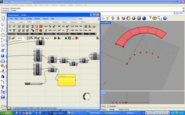
Now that i've got geometry to be subtracted from, let's create the positive: geometry "to be milled" , a simple sweep. For making this, Rhino, which uses NURBS, is several parsec far better than every other software i've tried. In fact it makes this operation in few seconds, just collect point defining a polyline track (in Revit this wouldn't have worked: because it has problems with singulatiries)...
.jpg)
...define and collect n+1 point...
.jpg)
...and draw a profile. This has not been immediate beacuse of using lists. It is indeed possible to cross reference of two or more lists. For instance: two lists containing two numbers each can define up to 4 different points (carthesian combinations, indeed). But is is not possible to directly manipulate the ORDER of these points; so instead of drawing a simple rectangle, the visual script draws that strange x.
.jpg)
It is on the other hand possible to manipulate lists indireclty. What i've done here is splitting the list in two halves, reversing the order of the second list, and merging two lists in just one.
What lists does not have is a direct control over list position of each item, which is automatic. Something that a design table has.
.jpg)
Sweep geometry is therefore ready. It is parametric and associative, in a very easily modifiable way. In my -not this great- experience, i used to re-draw each sweep, because their geometry, though free form design, is not always associative in revit -especially if controlled by parameters.
It is extramely easy to set up a paramether controlling the element we are producing -base or top: in this way we have just one visual script, while we will produce two different STL files.

Let's make solids subtraction!
No...it does not allow us doing this. The reason is that we need a closed geometry for making boolean subraction. This is a good proof that we are not working well: if we had made the subtraction like this, something impossible to predict would have come out of the STL file.
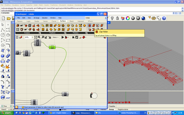
But fortunately, Rhino make us fill gaps using a Cap Holes operator. It is my opinion, but for 3d modeling rhino is what we call here "a sword": pretty good indeed.
Here we have our subtraction ready.

Since we want to fabricate this, let's make continue a bit first and last section.
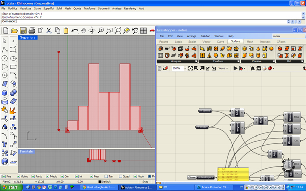
Last but not least, let's make holes for the wooden sheets. Not much to say on this point: just copy and paste the bit of script for making negatives.
Just one thing to notice: please note that sheet negative is somewhere shorter than pit one. This is obviusly a proble, since we would have had an open pit and farewell to scattered sound.
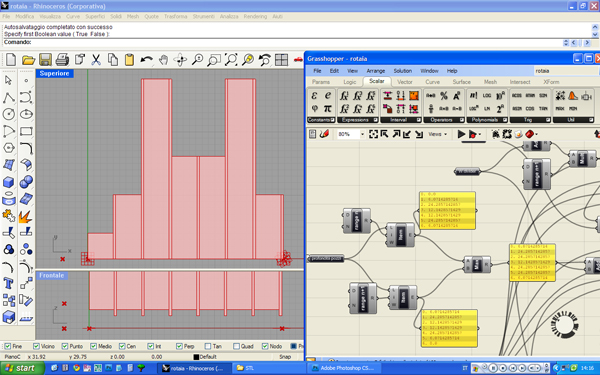
So we need to work on lists once more: departing from original pit sequence, let's make two parallel lists: one with the n-th distance, the other with the n+1-th. This is possible since lists are periodical. Let's collect both the values and choose the max one via a MAX operator.
In this passage i want to show how not immediate is to make conditional statements on Grasshopper: we've been lucky since MAX is an existing operator. For the cronicle: i'had tried and write a bit of script, unsuccesfully (since i do not know how to call lists).
Here we are...almost. The geometry is ready to be "baked", it is easily exportable (rhino is a "bin" program), parametrical and associative.
In box we see the architecture of this visual script. I find this visualization quite nice and pretty satisfying!

What we have to do now is
So, what i have now is a geometry ready to be fabricated, which is essentially a data, and a 3d which is still capable to give more fabrication datas, but we'll see this in the next post
ComponenteDevoto_Prototyping process (part 2: data out of geometry)
Commenti recenti